24dt L4f1 Wiring Diagram
Tokopedia thermometer gauge Contactor calm electrical Nema l6 30r wiring diagram
OEM VW Fuse Box (Mk4 Late 2002+)
L21 30r wiring diagram Wiring ac power receptacle diagrams sun Square d 8501kp12v20 wiring diagram
363-7697 installation ar-communication s/n l4f1-up an attachment 740b
Contactor diagrams30r nema l21 receptacle l15 30a 250v leviton [diagram] nema l6 30r wire diagramsConntek 60313 nema l6-30p assembly / replacement plug.
L6-30r duplex pdu whips, 30a, 250v, 3-wire underfloor pdu cables – pduWiring diagram cheat sheet K506 kinco plc connectors 30at dimensions cpusPlug wiring volt 240 diagram wire nema amp 30 220 20 l6 outlet prong outlets twist 30r lock plugs 250.

Switch plate min standard update
Wiring ac power receptacle diagrams america north sun301-8354 harness as-wiring s/n l4f1-up part of 354-8656 mirror gp-rear 239-1134 valve gp-ether starting s/n l4f1-up 24-volt, continuous partNema l21-30p wiring diagram.
L14 20r wiring diagramKinco automation L6 wiring nema wire 30a 30 250v neutral there l14 socket place plug twist lock then if only wires isn264-0148 sensor gp-speed s/n l4f1-up dual hall part of 341-3683 wiring.

Shop 24dt-l4f1
Mk4 oem fuse alternator239-1134 valve gp-ether starting s/n l4f1-up 24-volt, continuous part Oem vw fuse box (mk4 late 2002+)24dt-l4f1: weiss digital thermometer & light switch.
Instruments weiss250 volt outlets 459-9055 wiring gp-front s/n l4f1-up field installation 740b ejector43 l1 l2 com wiring diagram.
.png)
Vw jetta alternator wiring harness
L14 30r 20rContactor wiring diagram Circuit diagram wiring a contactor 2 pole contactor wiring diagram howキーエンス kv-e4r.
24dt-l4f1Accelerometer switch demo Weiss 24dt-l4f1 led temperature displayL4f1.

Wiring diagram sheet cheat diagrams
How to wire a nema l6-30-r 30a 250v socket.there is no place for theDigital thermometers with switch plate Amerikooler 24dt-l4f1 digital thermometer and light switch kit 120vJual themperature thermometer gauge control / switch.
.


OEM VW Fuse Box (Mk4 Late 2002+)

キーエンス KV-E4R - blog.knak.jp

239-1134 VALVE GP-ETHER STARTING S/N L4F1-UP 24-VOLT, CONTINUOUS PART

Circuit Diagram Wiring A Contactor 2 pole contactor wiring diagram how

L4F1 - Stiftung Missionswerk Heukelbach
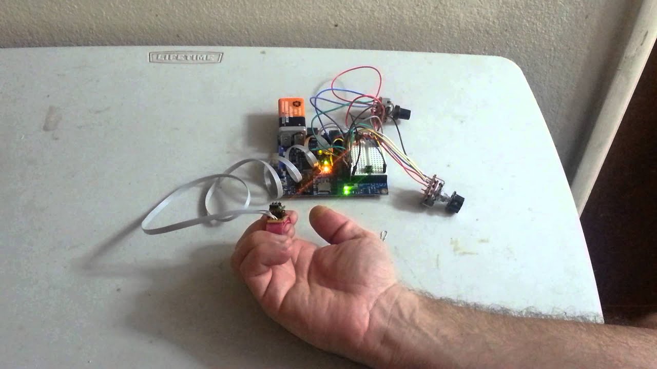
Accelerometer Switch Demo - YouTube

Wiring - AC Power Receptacle Wiring Diagrams